
Anamorphic Speckle Patterns: Improving DIC for Large Structures
When you try to measure deformations on large structures like aircraft wings or fuselages, you often face a fundamental problem: the camera can’t be positioned perfectly perpendicular to the surface. This “tilted angle” problem creates perspective distortions that degrade measurement quality in Digital Image Correlation (DIC).
A new paper published in Optics and Lasers in Engineering by Stéphane Hu and colleagues tackles this exact problem using a clever geometric solution: anamorphic transformation of speckle patterns.
The Problem: Perspective Distortions in DIC
Digital Image Correlation is a powerful optical technique for measuring deformations. It works by tracking how a random speckle pattern on a surface changes between images. But when the camera views the surface at a tilted angle, two problems emerge:
- Speckles appear distorted - What looks like uniform dots on the surface appears stretched or compressed in the camera view
- Correlation degrades - The DIC algorithm struggles to match distorted patterns, increasing measurement uncertainty
This is especially problematic for aircraft testing, where you might be measuring wing deformations from inside the cabin or ground-based cameras looking up at wings.
The Solution: Anamorphic Pre-compensation
The paper’s key insight: if you know the camera geometry, you can pre-distort the speckle pattern so it appears uniform to the camera.
Think of it like creating an anamorphic painting - the artwork looks stretched when viewed from the side, but appears normal from a specific viewpoint. Here, the “anamorphic” speckle pattern is designed to compensate for the camera’s perspective.
How it works:
- Geometric model - The known camera position and surface geometry define the perspective transformation
- Pattern generation - A reference speckle pattern is locally transformed according to this transformation
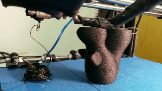
- Physical application - The anamorphic pattern is printed and applied to the test surface
- Standard DIC - No changes to the correlation algorithm; it sees uniform speckles
Experimental Validation
The researchers tested this approach on a planar target with controlled tilt angles up to 89.7° - extreme grazing angles representative of real aircraft testing scenarios.
Key results:
- Consistent uncertainty reduction - The anamorphic pattern consistently reduced matching uncertainty compared to regular patterns
- Improved 3D localization - Better precision in determining 3D positions of surface points
- Robust to angle changes - Benefits maintained even as camera incidence angles increased
Why This Matters for Aerospace
Aircraft testing often requires measuring large structures from fixed positions that create poor viewing angles. Traditional DIC setups struggle with these configurations. The anamorphic approach offers a practical solution:
- No camera repositioning needed - The pattern compensates for the camera angle
- Works with existing DIC equipment - No special cameras or algorithms required
- Extends measurement range - Enables testing from positions that were previously too distorted for reliable DIC
Future Work
While this study validates the approach on planar surfaces, the method is designed to extend to:
- Complex curved surfaces - Aircraft wings, fuselages, engine components
- Full-scale structures - Real aircraft testing applications
- CAD-based implementation - Direct mapping from digital models to physical patterns
The Paper
- Title: “Planar validation of speckle pattern optimization for large-scale 3D streamlined structures in stereo digital image correlation using anamorphic transformation”
- Authors: Stéphane W. Hu, Guilhem Marchal, Yvan Dilem, Denis Walch, Ilyass Tabiai
- Published in: Optics and Lasers in Engineering, 202(2026) 109773
- DOI: 10.1016/j.optlaseng.2026.109773
- Open Access: Read the full paper
Call to Action
- Is this research applicable to your work? The method works for any DIC setup with known geometry
- Want to collaborate? Contact the research team for details on the CAD implementation
- Found this useful? Share it with colleagues working in experimental mechanics
Technical Notes
For those interested in the implementation:
- The anamorphic transformation is computed offline - no real-time processing needed
- Python scripts are available for pattern generation
- The method works with standard DIC software (no custom algorithms required)
- Pattern quality depends on accurate knowledge of camera position and surface geometry
About the Research Team
This work was conducted at ETS Montréal’s Department of Mechanical Engineering, with support from Bombardier and MITACS. The research combines expertise in experimental mechanics, optics, and aerospace testing to solve practical measurement challenges.
Leave a comment