Anamorphic Speckle Patterns: Fixing DIC for Large Structures
Planar validation of speckle pattern optimization for large-scale 3D streamlined structures in stereo digital image correlation using anamorphic transformation, by Stéphane W. Hu, Guilhem Marchal, Yvan Dilem, Denis Walch, Ilyass Tabiai. Published in Optics and Lasers in Engineering (2026), 202(2026), 109773.
Why This Is Relevant for Aerospace
In aerospace structures, we still face a major measurement gap: we do not have an accurate way to observe the real deformation behavior of large structures such as wings or fuselage sections under realistic loading, especially in-flight. Instrumentation gives us local information, and simulations are essential, but we still need full-field experimental measurements to validate what the structure is truly doing.
This is exactly where Digital Image Correlation (DIC) should help. The challenge is that large structures force camera placements at non-ideal angles, and this is where standard speckle patterns start to fail.
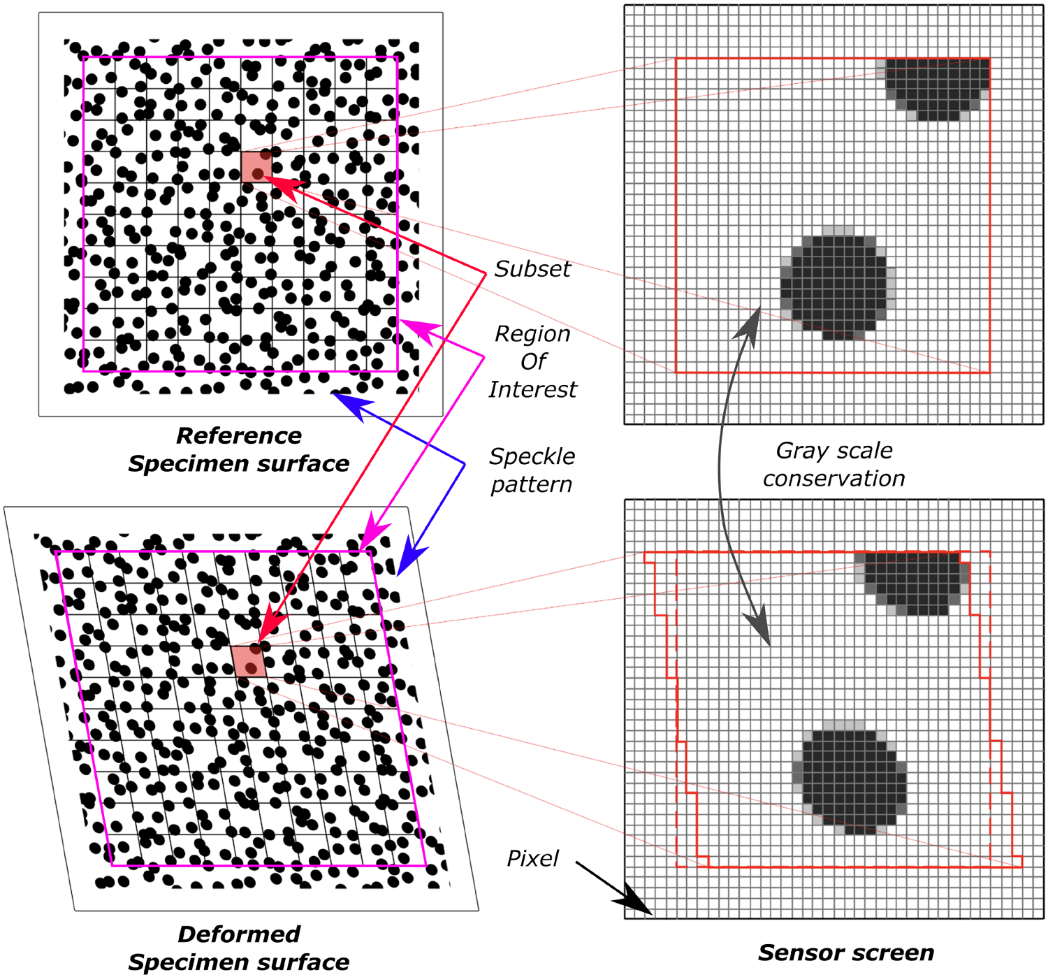
Figure 2: Perspective distortion effect on speckle patterns. Left: circular speckles viewed perpendicular to camera. Right: same speckles viewed from tilted angle: they appear deformed and non-uniform in size.
The Problem with DIC on Large Structures
Digital Image Correlation (DIC) is a standard tool for measuring deformations in experimental mechanics. It works by tracking a random speckle pattern on a surface between images. Using the changes in that pattern, we can measure displacements, and compute strains from them, with sub-pixel accuracy. But when we measure large structures like aircraft wings or fuselages, we often cannot position the camera perpendicular to the surface.
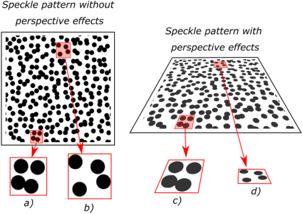
Figure 3: Anamorphic transformation concept. Shows how a circular speckle is geometrically transformed so it appears uniform from the camera's viewpoint, even when projected onto a tilted surface.
This creates a real problem: perspective distortions cause speckles to appear non-uniform in the camera view, degrading correlation quality and increasing measurement uncertainty.
The Anamorphic Solution
Our key insight is simple: if we know the camera geometry, we can pre-distort the speckle pattern so it appears uniform to the camera.
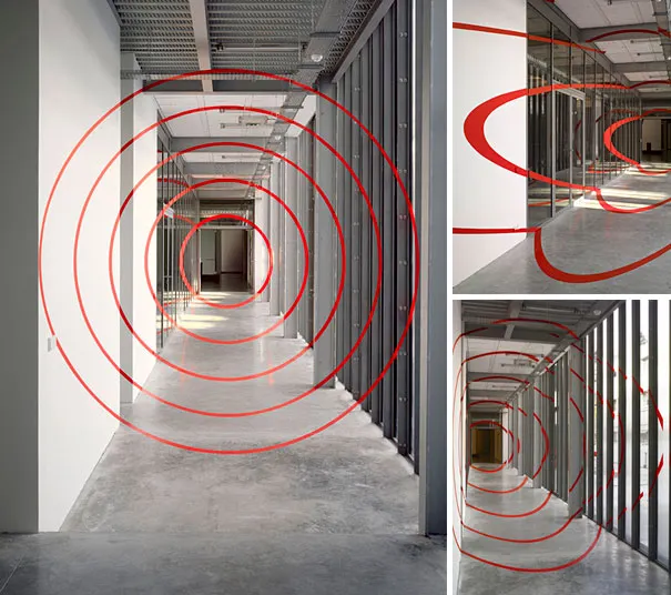
"Cinq Cercles Concentriques" by Felice Varini, Paris 2007.
Think of it like anamorphic art: the image looks stretched when viewed from certain angles, but appears normal from a specific viewpoint. Here, the anamorphic speckle pattern is designed to compensate for camera perspective, so the DIC algorithm sees uniform speckles.
We can illustrate this with “Cinq Cercles Concentriques” by Felice Varini: from most positions, the painted geometry looks fragmented, but from the designed viewpoint, it reconstructs into clean concentric circles. Our approach follows the same logic for measurement rather than visual effect: we intentionally distort the pattern on the structure so the camera recovers the right local speckle geometry.
How It Works
- Geometric model: Known camera position and surface geometry define the perspective transformation
- Pattern generation: A reference speckle pattern is locally transformed according to this transformation
- Physical application: We print the anamorphic pattern and apply it to the test surface
- Standard DIC: That’s the neat part! No changes to the correlation algorithm, it sees uniform speckles
Experimental Validation
We tested this on a planar target with controlled tilt angles up to 89.7°: extreme grazing angles representative of real aircraft testing scenarios. This scenario aims at preparing real in-flight experiments where a camera is fixed on the fuselage close to the wing and is filming the wing throughout the flight.
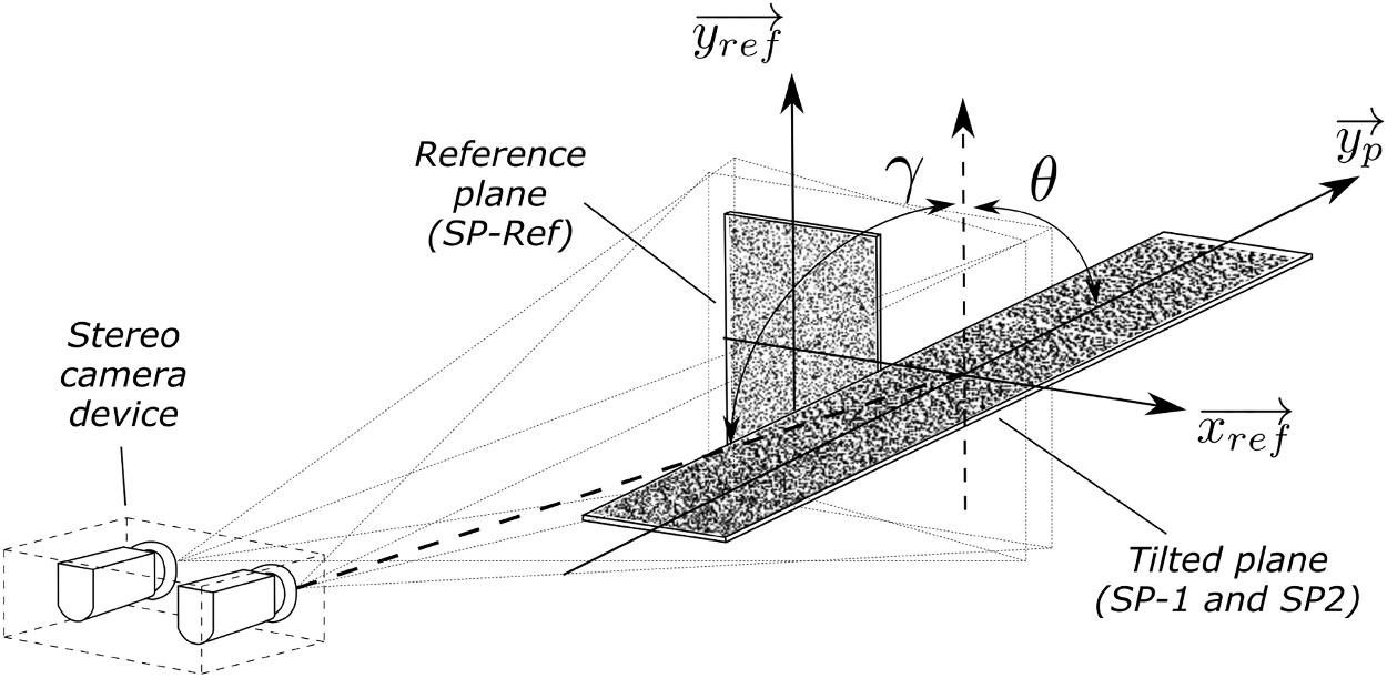
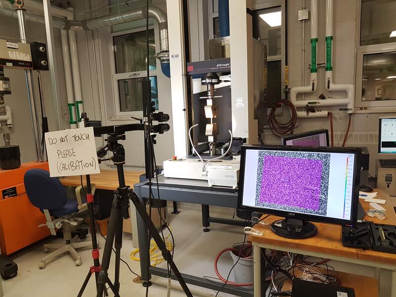
Figure 5: Physical setup. Wooden boards on variable-height tripods allow controlled tilt angles. Stereo cameras mounted on fixed support, large LED panel provides uniform illumination.
Key Results
In simple terms, when viewing conditions become difficult, our anamorphic pattern keeps the measurement stable. Across the full angle range, we get lower matching uncertainty and cleaner 3D reconstruction than with a regular pattern. This is exactly what we wanted and proves that applying anamorphic transformations actually improves DIC accuracy, or most specifically recovers accuracy.
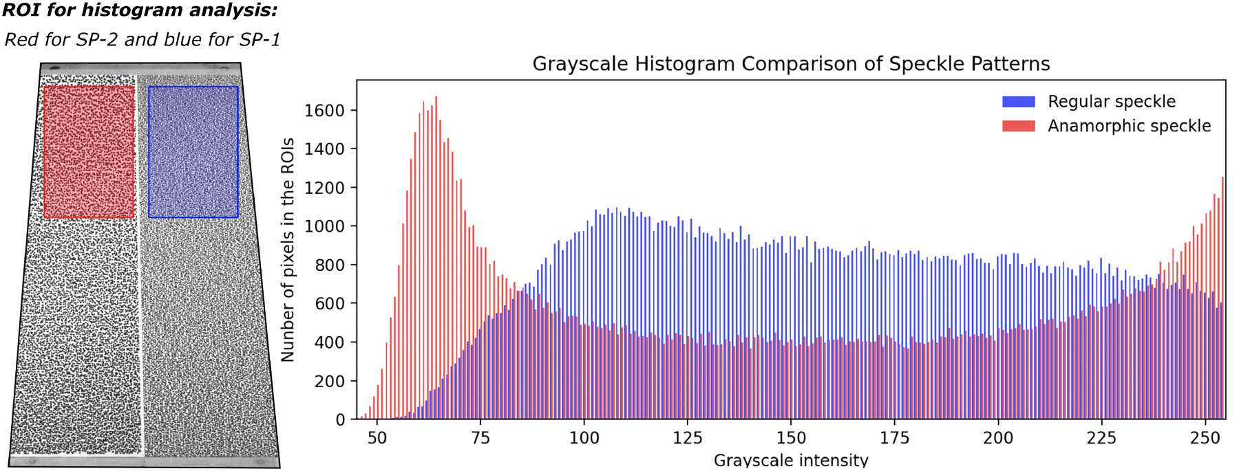
Figure 8: Main result: grayscale intensity over the rectangular area selected far from the camera (where the speckle pattern degrades the most). The red pattern (many black and white pixels only) is what a good speckle pattern looks like in DIC. The blue patter, obtained with a regular pattern, shows that most pixels forming the speckle pattern are in the grey area (not in the extreme of the grayscale intensity) which is not what we want for DIC as it makes the black and white pattern noisier.
- Lower matching uncertainty: The anamorphic pattern consistently reduced matching uncertainty compared with regular patterns
- Better 3D localization: We obtained more precise 3D positions of surface points
- Robust behavior at high incidence angles: Benefits were maintained as camera incidence angles increased
Why This Matters
For large aerospace structures, camera placement is constrained by geometry, test rigs, safety, and access. This is true in static ground tests, and it becomes even more critical in-flight, where instrumentation options are limited and full-field optical access is extremely challenging. In practice, there is currently no robust way to measure full-field deformation of large airframe structures in-flight with the level of confidence we want.
Our anamorphic approach provides a practical path for both static and in-flight configurations:
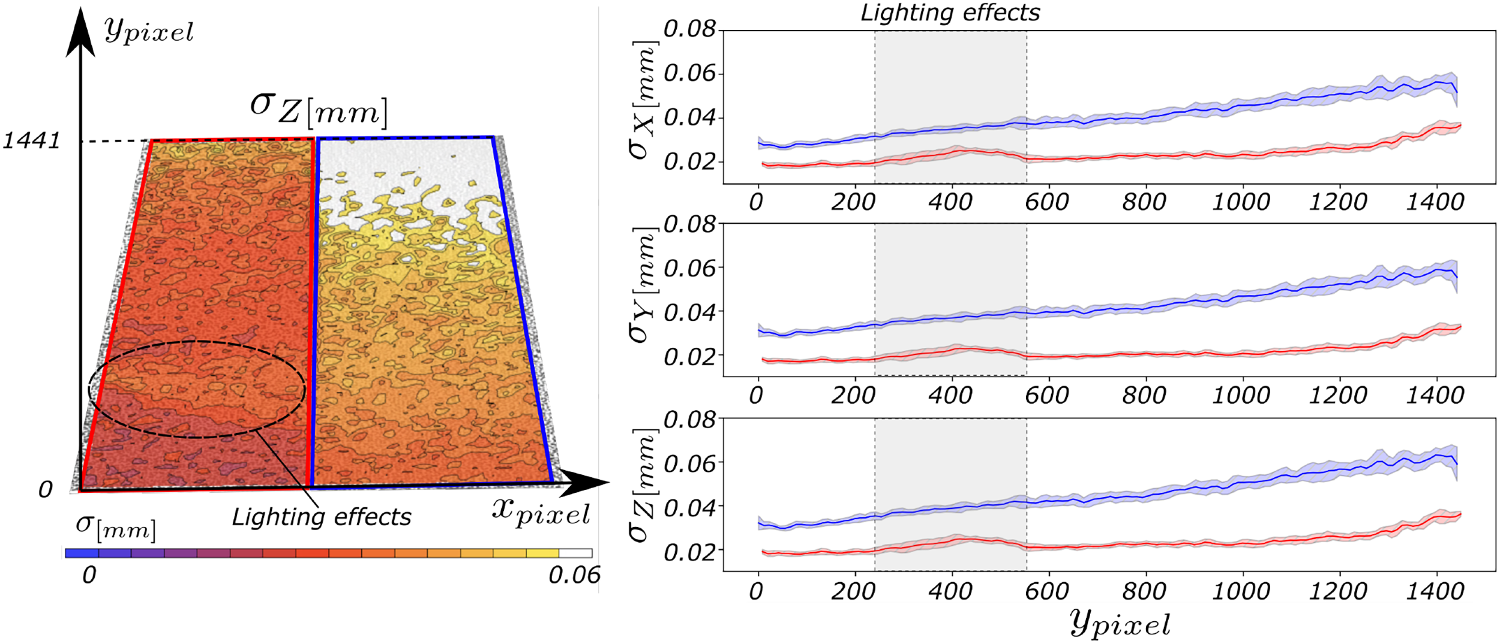
Figure 11: 3D point cloud comparison. The anamorphic pattern (SP-2, red) produces points that cluster more tightly around the best-fit plane compared to the regular pattern (SP-1, blue), demonstrating improved 3D localization precision. A lower σ value (X, Y and Z) yields more accurate DIC measurements.
- No camera repositioning needed: The pattern compensates for the camera angle
- Works with existing DIC equipment: No special cameras or new correlation algorithms required
- Extends usable measurement configurations: Enables testing from positions that were previously too distorted for reliable DIC
- Supports future in-flight measurement strategies: This is the direction we are developing next
Next Steps
This study validates the approach on planar surfaces, and we are now extending it to complex curved surfaces, including wings and fuselage sections, and then toward in-flight deployment scenarios. The transformation framework is generic and can be applied offline during pattern generation. We will soon be sharing results fo in-flight tests where this technique was used to obtain displacement and strains on a wing during a test!
Leave a comment